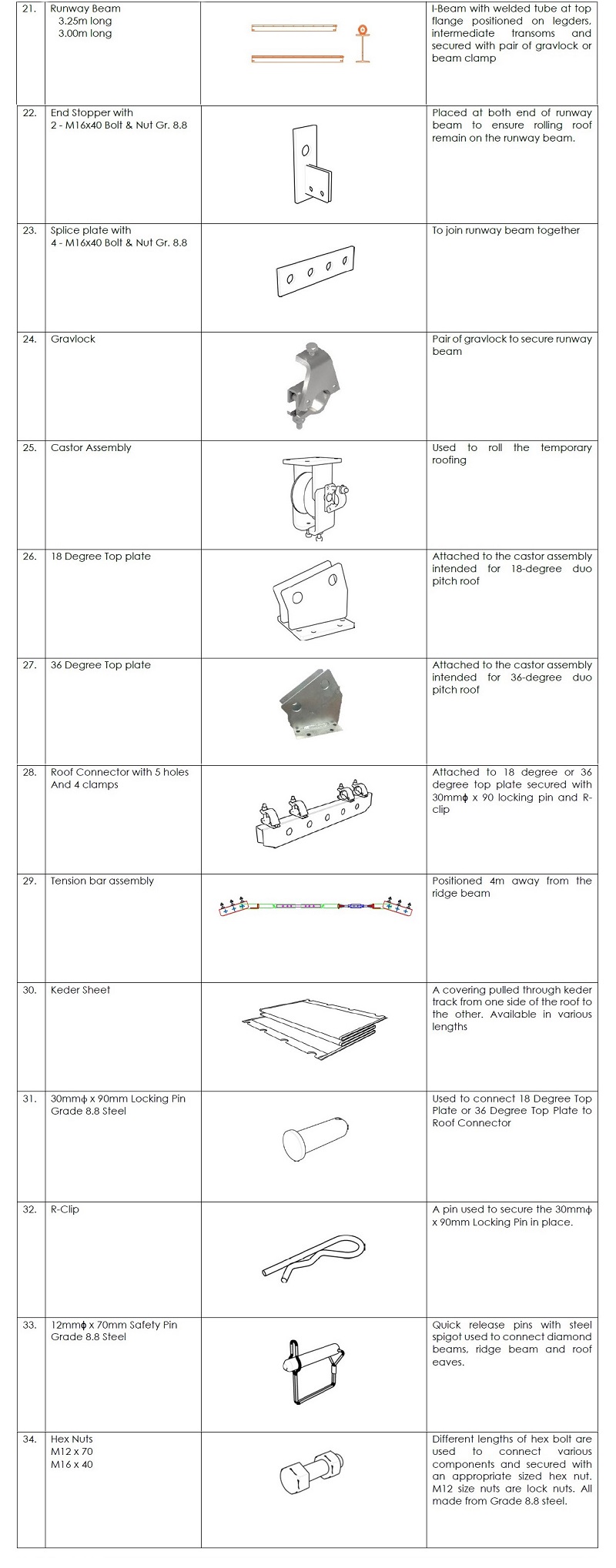
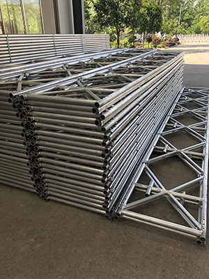
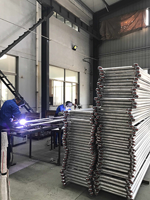
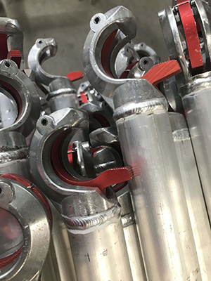
The connection between the Roofing and any support structure is to be in accordance with the design produced by a Scaffold Engineer.
Step 1
Ensure that the perimeter scaffold support is ready to support the crane-lifted roof in accordance with the design producedby a Scaffold Engineer
Step2
Establish a space where roof bays can be made on the ground. Once established, the space should be segregated to ensure the safety of the public.
Step 3
At ground level, create a temporary stepped working platform scaffold to be used in assembling craneable roof.
Step 4
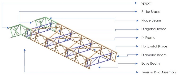
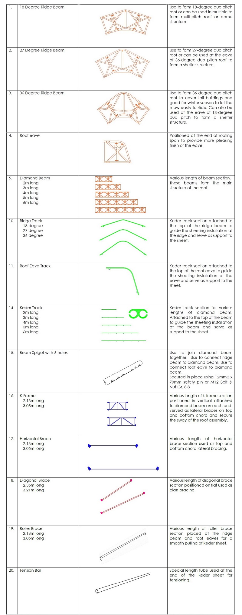
Establish the correct height of the ridge beam. Connect two ridge beams(track included) with the desired length of brace frames supported by horizontal tube and fittings. Secure the roller brace into the pockets provided.
Step 5
Attached diamond beams to the ridge beams using steel spigot with 6-Ø12mm x70 locking pins.
Step 6
Connect the diamond beams for desired length and attached roof eave at both sides. All joint connections using steel spigot with 6-Ø12mm4 x 70 locking pins
Step 7
Continue to install K-frame starting from the ridge down to the eaves at 2m interval.
Step 8
Install the horizontal braces in between of the K-frames at top chord to create a 1m lateral bracing for compression chord.
Step 9
Install the roller braces located at roof eaves.
E412 Oriental Innovation Center,N0.216 Jin Feng Road,Suzhou ,Jiang Su Province China I www.acescaffold.com I info@acescaffold.com
Step 10
Install the diagonal braces at 1m interval in zigzag arrangement starting from ridge down to eaves
Step 11
At this stage the first braced bay roof completed ready for craning.
Step 12
Attach the sling to its desired location as determined by the Scaffold Engineer. Four lifting points required with sling positioned to an angle not less than 70 degree from horizontal
Step 13
Lift the first fully braced bay into position and connect to the scaffold, ensuring the bay is correctly aligned. Secure the truss to the scaffold in accordance with the design produced by a qualified Scaffold Engineer.
Hand lines may be tied to the beams at the eaves, prior to lifting, to help guide the bay when lowering into position
Step 14
Create a second fully braced bay at ground level, by repeating steps 4 to 12.
Step 15
Lift the second fully braced bay into position. Horizontal Brace can be used at the eaves to establish the correct distance fromthe first bay. Secure the truss to the scaffold in accordance with the design produced by a qualified scaffold Engineer.
Step 16
The infill bay between the braced bays can now be completed Working progressively from the ridge down to eaves, install horizontal braces spaced at 1m interval for the top chord and 2m interval at bottom chord.
Step 17
Install the roller braces at the ridge beam and roof eaves inserted to the pocket provided.
Step 18
Continue the process until all bays are complete, and fixed to the supporting structure in accordance with the design producedby a qualified Scaffold Engineer.
Step 19
Pull the keder sheet over the track and secure to the scaffold. Refer to Sheet Installation. The sheet can be installed sequentially once at every bay.
